You'll need a big whip..... I built my own and it's just under 3Mtrs long. It is mounted on the roof of the car on a cross member bolted to the luggage rails. This is the right place for any mobile antenna!

This is what the "Vaeriel" mobile whip looks like on the car. There are little guy-lines to stop it swinging from side to side or bending back too much at speed.
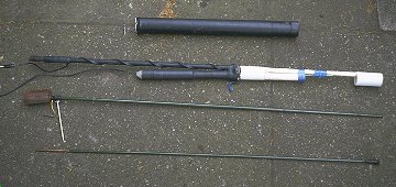
These are the component parts of the Vaerial whip. At the top is the coil wound on a 470mm long piece of 42mm plastic "solvent weld" pipe (this is stiffer than the ordinary stuff) with about 304 turns of 1.25mm enamelled wire (for 160) and covered in heat shrink sleeving. Next down is the base section (600mm length below the coil) which is based on a 10mm diameter fiberglass rod the bottom of which is wound with thick copper wire and covered in heat shrink. The plastic tube containing the motor, the lead-screw and the copper slug (seen below the base section) is attached using "Isopon" fiberglass resin car filler. The 150mm length of 12mm copper water pipe is driven up and down inside the tube by the motor and lead screw (M4 threaded nylon rod) and hence in and out of the coil. This gives an adjustment range of 50kHz on 160 Mtrs and 100kHz on 80. At the bottom of the picture are the two parts of the ex army "tank whip" (copper plated steel tube sections total 1770mm), the section which fits into the top of the coil has a small telescopic whip sticking out, this allows for adjustment of the centre frequency of the system.
The 80M coil has about 100 turns of 1.5mm wire, close wound on the bottom of another identical piece of tubing, it would be better to wind the coil near the top of the former but then the copper slug wouldn't go inside the winding!
The system will stand the 400W from the mosfet PA but watch out for sharp edges at the top of the whip. Smooth them off and insulate well with self-amalgamating tape or you'll get a firework display!
I have also used a small loop aerial on the car which worked surprisingly well. The loop is made of 22mm copper water pipe and is a rectangle with 1m vertical sides and 1.6m horizontal pieces. The centre piece which supports the coupling loop is made of some sort of plastic material.

A large vacuum variable capacitor with a maximum capacitance of 2000pF lives in the plastic box at the bottom. The loop will tune from just below 160m up to the 40m band.
The coupling loop is made from 8mm copper pipe and is very critical to set up so as to maintain a good match over the whole tuning range.
The loop can be raised and lowered with a 12V motorised jack. Thanks to Malcolm G4FQI for assisting with the mechanical arrangement.

These chaps all operate 160Mtrs and most have mobile stations. The photo was taken by Graham, G3XTZ at Woburn radio rally in August 1997.
From left: G4ZOW, G3NMZ ,G4WBV, G3JFH, G3OLB, G4BXM, G4ENB, G3YXM, G4CBQ, G4HKS, G4TRT (sitting), G3VMD, ..?.. ,G3TSO, G3XTZ.
The rig I use in the car is the Kenwood TS-480 which is convenient as it has a detachable front panel that can be fitted in the dash whilst the rig lives in the back of the car. Best daytime mobile to mobile DX on 160 is from Stoer point North of Lochinver in Scotland to near Bath on the M4 motorway where Richard G3CWI/M was travelling home. That's 450 miles at half past two in the afternoon in October! Best DX overall was to AB4VV early one morning when I used to be keen.
The aerial match will vary and some rigs like the Alinco DX70 are very keen to reduce power if the SWR isn't perfect. It's a good idea to de-sensitise the SWR protection on the DX70 to make it useable in the car. Take the bottom cover off the rig, (lots of screws!) remove the tinplate screen and find the filter board, the one with the toroids on it. Near to CN507 you will see a plated-through-hole marked "REV". Solder a small 100k trimpot from this point to the ground-plane. Starting with the pot at max resistance, tx into a mismatch of 3:1 or so via a bridge and adjust the pot until you get about 12W reflected. This should not be done if you are worried about invalidating the warranty! As a rough guide, the resistance from "REV" to the ground plane measures about 30k with the pot set up. I have had no problems with my DX70 since doing this and it did enable me to keep on the air when driving past lamp-posts etc.....
I have also constructed an HF whip to cover 20M to 10M, a bit like the outbacker with jumper leads to short out bits of the coil. The basic whip has a coil wound with 3/16" copper strip at the top of a 5ft fiberglass tube. A stainless steel whip section sits on the top. The basic whip resonates on 18MHz and is brought down to 14MHz by connecting a small coil at the base of the aerial. For 21MHZ some of the coil is shorted and for 28MHz it all gets shorted! This seems to go OK, I worked JA the second time out on 18MHZ! I have even tried mobile on 136kHz! Not really a practical proposition.

The stateside QSO was made with the assistance of one of my "Throbbatron" MosFet amplifiers, it's the box with the handles on nearest the side of the car. The base-station version of it is detailed on the shack page. The mobile version runs from 24 Volts using a small "parallel on receive - series on transmit" extra battery (can just be seen between the Throbbatron and the KLM 2Mtr PA) and gives 400W. You can just see the dear-old Atlas 180 in this picture, not in the car anymore but I won't part with it!
Mobile on 136kHz!!!
(well almost)
It can be done! All I have to do now is get the thing solid enough to operate on the move. With the setup shown "static mobile" in the Worcestershire countryside I have worked GW4ALG in Chepstow (102km), G4HYU in Louth (166km), G0UPU in Cheltenham and G3YMC in Bracknell. I have also had a good report from G3KEV in Scarborough (237km).

The amber coil is a huge 23mH job which, even with the 12ft tank-whip on top wasn't quite enough to resonate on 136kHz. I had to add some horizontal(ish) rods just above the coil and a bit of extra inductance in the form of my /P loading coil and variometer seen on the roof. The portable TX was used and, with about 300W of RF I was able to get almost 1A of aerial current with only the car body for earth. I have since used a longer top section of 15ft and it then loads OK without the extra coils. All I have to do now is reduce the height to 14ft overall and we're really mobile........
The Golden Rules of Mobile
If you follow a few simple rules when installing your mobile setup you will avoid the common pitfalls.
Power Supply
A 100 Watt mobile rig will draw around 20 Amps. Thick cable must be used, 6mm copper is an absolute minimum and the positive should be run direct to the battery terminal via a fuse. The fuse I use is a short piece of 1.5mm wire between two sections of terminal strip with the short cable to the battery wired to one side and the one to the rig on the other. Run the power cable through a suitable hole in the bulkhead from the engine bay into the car. It is always difficult to find a suitable hole in modern cars but try where the clutch or accelerator cables come through, there should be some room to make an additional hole in the rubber bush. Use electrical tape or cable ties to fix the cable on its route through the engine bay to the battery. Everything rattles about so much in there it's easy for the cable to drop onto some hot component or chafe against a sharp edge which could cause big sparks! Just remember not to connect the battery until you've got the cable all pulled through.... sparks again. When routing the cable inside the car it is usually possible to hide it under the carpet or plastic trim panels until it emerges at the position where the rig is to be fitted. The hardest part is now going to be finding a good ground connection for the rig amongst all the plastic. I usually cable the negative supply to the car body, some would advocate cabling it back to the battery but, for RF reasons, you will need a solid ground on the rig anyway so you might as well make it the supply and save a second run of thick cable. Good places to look are seat mounting bolts and safety belt mounting bolts, scrape the paint off the bodywork where the connection will be made, use a large earth tag and do the bolt up tightly. Obviously the negative cable should be at least as thick as the positive one.
Positioning
If you don't have one of these super new radios with detachable front panels, you will need to mount the rig where you can get at it. This is no easy task in a modern car but it is worth investigating which bits of the dash, such as the glove box, can be removed without damage to reveal a suitable space. Otherwise it's "jam it between the front seats" time. I would strongly advise against mounting it under the dash where you or your passenger's knees may come into contact with it in a crash... Most modern rigs are immune to reasonable amounts of vibration but especially with older non-synthesised rigs it is not a good idea to fix them down too firmly, use some padding.
The Aerial
You'll need one of these! The best place to mount it is in the centre of the roof. If you can't fit a luggage rack or similar device then a gutter mount on the edge of the roof is next best for a small aerial. For the DX chaser with no roof rack a large whip can be fitted to the tow hitch or similar place SO LONG AS THE LOADING COIL IS AT LEAST AS HIGH AS THE ROOF. The feed to the aerial should be via coax cable, I use very thin RG174 for ease of feeding it through the door seal and it stands 400W with very little loss over the short length required.
The braid of the coax must be grounded as close to the base of the aerial as possible. If you are using a luggage rack or a frame between roof rails as I do, then run earth straps between the metal frame parts to ensure good contact. A good place to find a ground point near the roof is the top seat-belt mounting point just inside the door. You can run some thinnish connecting wire in through the door seals with no problems.
A good big mobile whip on resonance on the LF bands will present an impedance of about 20 Ohms to the rig, it won't like this! Any 160/80/40m whip that gives a perfect match on resonance is LOSSY, don't believe the hype! To feed your 20 Ohm super-whip you can either use a transformer, available from retailers or home made, or use capacitive matching. The principle of parallel capacitive matching is, I am told, that the capacitor plus some of the inductive component of the aerial form an L-match to transform the impedance up to 50 Ohms. This is why adding the capacitor actually increases the resonant frequency a few kHz. The capacitor should be wired between the base of the aerial and ground, at the aerial end of the coax. If this means that it will be outside the car then weatherproof it with varnish or silicone rubber compound. Silver Mica capacitors are best for the job, I have a selection fitted with 4mm banana plugs which I plug into sockets at the base of the whip depending on the band in use.
Capacitor values for a 3Mtr whip
| 160 Mtrs | 2200pF |
| 80 Mtrs | 1300pF |
| 40 Mtrs | 600pF |
As you can see, these very roughly double in value as you halve the frequency, so once you have found the value for one band you can make a good guess at the adjacent one!
Suppression
This can be tricky. There are three ways that interference can get to receiver, by direct radiation from the ignition system etc., by radiation from the car's wiring loom which is carrying interference and by conduction into the rig down the power leads. Supply-bourne interference should not occur on a good radio but, if it does, it is simply cured by fitting a large electrolytic capacitor (10,000uF) in parallel with a high quality polyester 1uF straight across the supply terminals at the back of the set. A few turns of thick wire round a ferrite rod can also be tried in series with the positive lead just before the capacitors.
The first type of interference (direct radiation) is best tackled by ensuring that the car's bonnet (hood) is well grounded. Put earth straps across the hinges and ensure that the bonnet shuts tight. If you car has a plastic bonnet you're in trouble! Try lining it with cooking foil glued inside and earth this at the hinge end with straps. The ignition system should have some suppression fitted as standard, resistive leads and/or plugs etc. but it's worth checking that they haven't been changed by a previous owner, resistor plugs usually have an R in the type number. If it proves troublesome, braid from thick coax can be slid over the HT leads and grounded but the leads must be in perfect condition otherwise you will get flash-over and misfires.
The second type of interference is the most common. All sorts of bits of electronic stuff scattered around the car can kick out noise that finds its way to the receiver by radiation from the wiring loom. Tracing the source is tricky, does it start when the ignition key is turned on or only when the engine is running? If it is there without the engine running then pull fuses out of the fuse box until it stops, hopefully this will lead you to the culprit (instrument regulators are a prime suspect). Once you find it you should be able to decouple it with a 1uF capacitor on the supply side straight down to ground. I stopped one noise source by decoupling the fuse which fed it, in the fuse box, no need to take the dash apart. Some cars seem designed to radiate interference, one of mine had the ignition coil mounted on the bulkhead, the spark-current had to flow from the coil to the engine block via the HT leads and then back to the coil via a strap at the bottom of the engine and up through the bulkhead! A reduction of over 10dB was made when the coil was insulated from the bulkhead and connected, with a thick strap, straight to the cylinder head.
There are no sparks in a diesel engine so the
interference my bit a little less, and you'll get better fuel figures, but
modern diesels have just as much electronics as their petroleum powered
brothers so the difference isn't as much as it once was.
Finally to the
alternator (generator), which can cause hash (use a filter) and engine
management electronic "black boxes" which can cause all sorts of noises but are
best left alone unless you know what you're doing! About all you can try is to
decouple the supply to ground right by the box and route interconnections
separately from the rest of the wiring loom, especially the lead to the
coil.
Goodness knows what we do about multiplex wiring systems and Xenon
headlamps though...
I hope this has been of some interest, see you
on the bands.... /M of course!
© G3YXM 1998-2020 updated sporadically!
