PA0LQ
audio filter and mains QRM noise blanker
The following is a translation of a description I made
for Electron of June 2000; the magazine of the Dutch amateur radio society
VERON (to be translated as Society for experimental radio research in the
Netherlands). Audio filter and noise blanker were designed and used by
Harry Grimbergen, PA0LQ.
Audio
filter
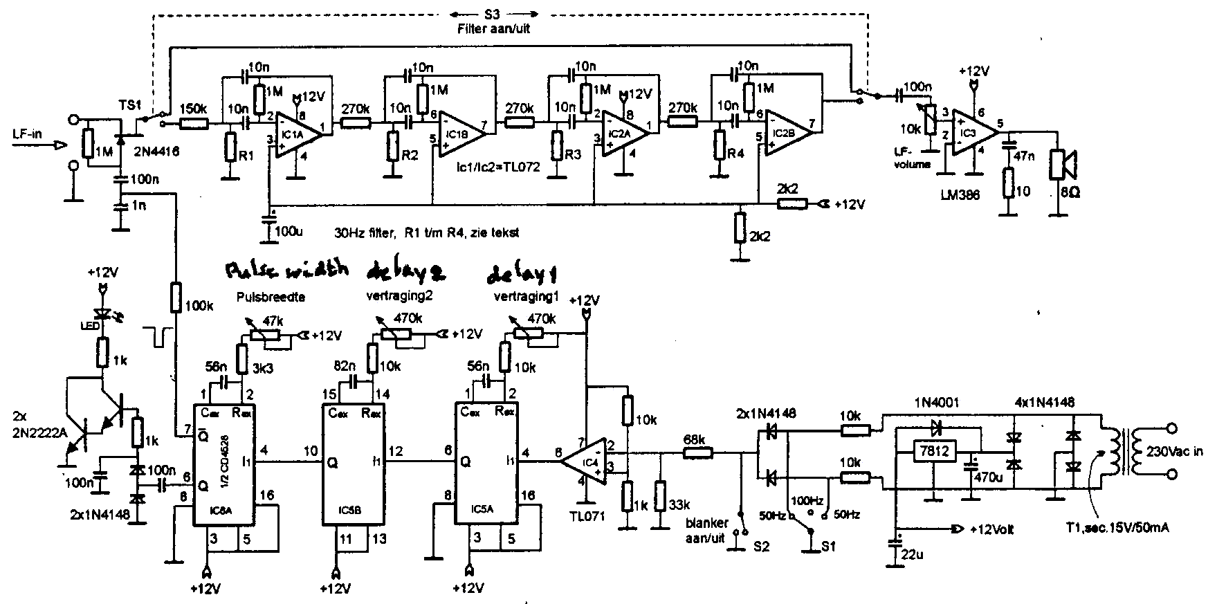
The upper part of the circuit diagram shows a
non-ringing audio filter with 1000 Hz centre frequency and 30 Hz bandwidth.
The opamps are of the low noise type.
The values of resistors and capacitors may deviate up
to 10% from the indicated values, as long as they are stable. For the
capacitors polystyrene or mica types are to be preferred.
R1...R4 determine the resonance frequency of the four
filter sections. Their reactance is about 180 ohm. To find the exact values
they are temporarily replaced by variable resistors. The filter is fed from an
audio generator of which the frequency is measured by a counter (its dial
cannot be read with sufficient accuracy). The output voltage is indicated by an
oscilloscope or a VTVM. The resonance frequencies are now adjusted as follows:
By R1 to 966
Hz
By R2 to 982
Hz
By R3 to 1018 Hz
By R4 to 1034 Hz.
When tuning is completed the value of the resistors is
measured and the variable resistors replaced by metal film ones, or a
combination of such resistors. Even the best variable resistors are not stable
enough for this application.
Noise
blanker
Harry, PA0LQ, suffered from pulse interference that
was related to the mains frequency, as caused by light dimmers with triacs or
thyristors. He therefore made a noise blanker that is shown in the lower part
of the circuit diagram. The system does not help against interference from
fluorescent tubes, energy saving lamps and electric motors with a commutator,
as used in electric shavers and other appliances.
The blanker functions as follows.
By means of two resistors and diodes half-sinewaves
with frequencies of 50 or 100 Hz are derived from the secondary winding of T1.
The two 50 Hz voltages that can be selected differ in time by half a period of
the mains signal. Opamp TL071 converts the voltages into square waves that
drive two monostables in cascade. Then follows a third monostable that
determines the width of the "hole" that is made in the signal.
Variable resistors "Pulse width", "Delay 1" and "Delay
2" permit to position the blanking pulse exactly on the interference
pulse. A LED indicates when the blanking pulse is present. The blanking pulse
drives the gate of TS1, used as a switch.
The selectivity of the 30 Hz filter causes the holes
to be refilled almost completely. Readability of CW is affected only when more
than 20% is cut by the blanker.
Also for
LORAN?
John Rabson, G3PAI, asked me whether the PA0LQ noise
blanker could also be used on LORAN signals. PA0LQ thinks this is possible but
the blanker must then be driven by LORAN pulses that come from a separate
receiver, tuned to 100 kHz. I think that this could be a rather simple
receiver, for instance of the TRF type. It should not be too selective in order
to preserve the shape of the LORAN pulses.
Dick Rollema, PA0SE
